
Products
Home > Products > Mineral Processing Equipment > Flotation Cell
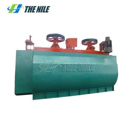
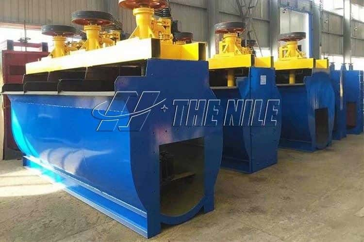
Processing Materials: The flotation cell is suitable for roughing and cleaning operations in large and medium-sized concentrators. It's mainly used for separating non-ferrous metals, ferrous metals, and non-metallic minerals with the particle size range of the selected materials are 0.3-0.01mm (- 0.074mm particle size content > 50%).

Working Principle of Flotation Cell
When the impeller of the flotation cell rotates, the pulp in the tank is sucked into the impeller blade from the bottom of the impeller through the end of the tank. At the same time, the low-pressure air supplied by the blower enters the air distributor of the impeller cavity through the air duct, air regulating valve, and hollow spindle, and enters the impeller blade through the hole around the distributor. After the ore pulp and air are fully mixed between the impeller blades, they are discharged from the upper half of the impeller. The discharged ore flow moves obliquely upward, stabilized and oriented by the stator installed obliquely above the impeller, and then dispersed into the entire slot. The mineralized bubbles rise to the surface of the tank to form a foam, the foam flows into the foam tank by itself, and the slurry returns to the impeller area for recirculation.

Advantages of Flotation Cell
1.The impeller of the flotation cell is a kind of conical impeller with the blades inclined backward at an angle, which has a strong stirring ability and simple structure.
2.A multi-hollow cylindrical air distributor is installed in the impeller cavity of flotation cell, the air is evenly dispersed and the air slurry is well combined.
3.The impeller diameter is small, the circumferential speed is low, and the power consumption is small, which can save energy by 30-50%.
4.The ore particles are well suspended and the flotation index of the flotation cell is high.
5.The U-shaped tank body is adopted, with fewer tailings deposits.
6.The wearing parts have light wear and long service life.
Technical Parameters of Flotation Cell
Model | Volume | Impeller diameter | Capacity | Power of motor(kw) | Four chutes | Single chute overall | |
Strring motor | Scraper motor | ||||||
XJ-0.13 | 0.13 | 200 | 0.05-0.16 | 1.5 | 0.55 | 1272 | 1120*1140 |
XJ-0.23 | 0.23 | 250 | 0.12-0.28 | 1.5 | 0.55 | 1558 | 1190*1238 |
XJ-0.35 | 0.35 | 300 | 0.15-0.5 | 2.2 | 0.55 | 1720 | 1350*1327 |
XJ-0.62 | 0.62 | 350 | 0.3-0.9 | 3 | 1.1 | 3041 | 1535*1760 |
XJ-1.1 | 1.1 | 500 | 0.6-1.6 | 5.5 | 1.1 | 5204 | 1970*2088 |
XJ-2.8 | 2.8 | 600 | 1.5-3.5 | 11 | 1.1 | 9295 | 2450*2295 |
XJ-5.8 | 5.8 | 750 | 5-7 | 22 | 1.5 | 13597 | 3250*2485 |